
Problems unloading and feeding the hydrated lime
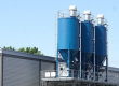
Duke Energy , Cayuga, Indiana is a coal-fired power generation station built in 1970 and upgraded throughout the years. The power plant has a capacity of 1,104 megawatts and supplies steam and power to the plant’s neighbor; a packing product manufacturer whose raw material is 100% recycled pulp products, as well as the surrounding counties. The station has an inside water treatment plant that uses hydrated lime to regulate the pH of their processed water. The hydrated lime is stored in two storage silos equipped with external vibrator unloaders, and obsolete feeding and slurry system.
The hydrated lime system was composed of two independent storage silos, both equipped with external vibrator unloaders. On each silo, the outlets are connected to a gravity by-pass that “diverts” the lime into two volumetric screw feeders, metering the dry chemical into 10 gallons lime slurry make-up tanks. Over the years, one of the silo systems had been completely disassembled and the plant worked on one silo and slurry system. To ensure optimal pH regulation, the coal-fired plant needed to find a better way to feed the hydrated lime into their slurry process.
One of the issues of the lime pH regulation system was the excessive noise and vibration created by the unloader vibrators. The vi
brators’ noise was over 100 decibels and the emitted vibrations not only shook the entire silo structure, but also compacted the dry chemical, increasing its density and created erratic unloading. The bypass connection to the feeders was not efficient and the feeder could never guarantee a continuous and accurate metering, neither meeting the new site feed rate requirements.
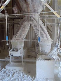
Overall, the feeders and the slurry tanks were not protected nor enclosed, resulting in hazardous and dusty working conditions. Most of the protection covers and lids had been removed to regularly maintain the defective and unreliable equipments, leaving exposed moving parts of the system without operator protection. The increase of power demand and plant extensions made
this existing feeding and lime slurry make-up system completely obsolete and unsafe for actual regulations.
Finding the best Feeder system
The engineering firm has worked with many power generation plants for flue gas treatment, as well as wastewater treatment facilities for pH regulation throughout the United States. The Chicago-based office servicing the North American market, supplies systems for discharging, conveying, weighing, and feeding dry bulk solids for the above-mentioned industries, as well as metallurgy, mining, pharmaceutical, and many bulk handling system processes.
“At first, they only wanted a bigger volumetric screw feeder, thinking that it would solve their feeding problem,” said Patrick Esor, Sodimate General Manager. “However, I told them that even if they installed a new volumetric screw feeder they wouldn’t have control of the material discharged from the silo, because the vibrators are not correlated to the feeder speed and would still cause inconsistent unloading into the system. I also told them that proper slurry mixing cannot be done in such small slurry tanks, and ncreasing the slurry concentration would clog their piping pretty fast. So I proposed to them that along with the screw feeder, I would provide a complete mechanical silo discharger and a new lime slurry tank for adequate slurry concentration and feed rate. Finally, I finally suggested interconnecting both silos into only one slurry tank to work as a stand-by/duty process.”
The new discharge and feeding system
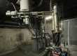
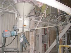
In January 2010, the discharge and feeding system arrived at the power plant where it was quickly and easily installed below one of the new silo’s cone section. The system consists of two (one per silo) arch breaker DDS 400 mechanical silo dischargers, two correlated screw feeders, one isolation injector connecting both feeders and one slurry tank. The arch breakers provide mechanical agitation inside the silo cones, without air injection (fluidization) or vibration (bin activator or vibrators), and eliminate arching, bridging and/or rat-holing phenomena, to ensure continuous material discharge to the screw feeder. The mechanical unloader can be used with large silos, big bag unloaders and small storage hoppers.
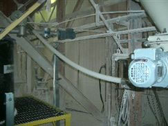
The arch breaker has an 8-inch-diameter inlet connected to the silo cone outlet flange holding a 16-inch-diameter cylindrical body hopper used to maintain a constant density of the product discharged from the silo. Located at the bottom of the hopper is an opening inlet for the volumetric screw feeder, a single-speed motor mounted outside the arch breaker’s body drives the mechanical silo discharger and two sweeping arms that fill the dry chemical into the screw inlet. The three-foot-long vertical shaft can be set to rotate from 7 to 50 rpm, depending on the product density and discharge rate. Several flexible blades mounted at intervals on the shaft extend out horizontally into the silo cone to just near the inside wall slope.
The 7-foot-long screw feeder is a 1.5-inch-diameter shaftless screw (flexible) and is installed directly below the mechanical arch breaker discharger. The screw feeder’s variable-speed motor allows it to feed material from 50 to 150lb/h. The lime fed from the screw feeders is then dropped into the isolation injector that prevents the slurry humidity to be in contact with the hydrophone dry lime. The dry chemical is then injected into the new 500 gallon slurry tank. The PLC controls the arch breakers, screw feeders, injector and slurry mixer operation, and is programmed to match the plant pH requirement by adjusting the speed of the feeder’s motors.
During operation, the arch breaker, injector and slurry mixer operate at a fixed speed and the screw conveyor operates at a variable speed determined by the signal called up on the PLC. As the mechanical arch breaker rotates inside the silo cone, its flexible blades condition the material to not bridge, arch or segregate as if it was used with vibration systems, and allows it to easily discharge from the silo into the arch breaker hopper. Since the arch breaker’s body is larger than the silo cone discharge opening, the material’s bulk density remains constant before entering the screw feeder, which helps maintain volumetric feeding accuracy.
To ensure that all the material in the arch breaker body hopper moves into the screw feeder, two rigid sweeper arms are mounted onto the vertical shaft about 0.5 inch above the arch breaker’s bottom. The arms extend out horizontally in opposite directions, and as the arch breaker operates, they rotate with the vertical shaft and continuously move the material into the screw feeder inlet. Since the screw flights are always 100 percent filled with material, the screw feeder is able to consistently feed the material volumetrically to the isolation injector with ±2 percent accuracy, providing a controllable material stream to the slurry process. der, two rigid sweeper arms are mounted onto the vertical shaft about 0.5 inch above the arch breaker’s bottom. The arms extend out horizontally in opposite directions, and as the arch breaker operates, they rotate with the vertical shaft and continuously move the material into the screw feeder inlet. Since the screw flights are always 100 percent filled with material, the screw feeder is able to consistently feed the material volumetrically to the isolation injector with ±2 percent accuracy, providing a controllable material stream to the slurry process.
The isolation injector is made of stainless steel with a bigger and reinforced screw and driven by a more powerful motor. The isolation injector will turn faster and guarantee that every solidified chunk resulting from the lime and moisture chemical reaction will be conveyed into the slurry tank. This prevents lime build up into the outlet screw feeder chute that results from snapping the augers.
The slurry tank is equipped with an agitator mixer and anti-vortex blades inside the cylinder. This increases the turbidity; hence reducing the slurry mixing and retention time. No electrical monitoring components are inside the tank to prevent lime coating and unreliable level reading. A float is simply connected to a counter balanced magnetic weight, where a reliable magnetic detector will read the signals for batching preparation.
There were no skid pumps installed, as it was Duke Energy’s desire to feed the lime slurry gravimetrically.
Successfully controlling material silo discharge and Lime feed system.
Since installing the new mechanical discharger, feeders and slurry system, the power plant no longer has erratic discharge and accurately matches the lime slurry feed rate to their pH regulation needs. “Improving the discharge and feed rate from the silos has given us better control of the slurry mix into the downstream water flow, which improves the pH regulation performances because we can better regulate the lime feed rate according to the pH fluctuation” said a Duke Energy Project Engineer. “In addition to better discharge and feed control, the overall quality and assembly of the equipment allows the process to run without operator supervision and is completely dust free. The system was also pretty easy to install, and it took longer to dismount the old equipment than retrofit the new one. You just follow the step-by-step manual, connect the parts all together in a logical and easy-to-mount order and you’re done.”